Did you know Verbotics Weld can be used to program the advanced welding functionality in your robot? Multi-pass welds, weaving, and through-arc seam tracking all can be programmed directly from the application. This post will look at programming seam tracking functionality using Verbotics Weld.
Seam tracking may require additional options for your robot. Contact your preferred robot supplier to determine if your robot has seam tracking capabilities.
How Tracking Works
Seam tracking works by measuring the electrical characteristics of a weld on each side of a weave to determine how well it is tracking to a seam. Typically this will be a V-groove or fillet weld so there is some change between wire stick-out between the centre of the seam and each edge.
Verbotics supports outputting the weld instructions to allow arc tracking directly within the application. You just need to type in the tracking settings you would like to use as specified by your robot manufacturer. For example:
- ABB you enter the trackdata. E.g:
[0,FALSE,10,[0,20,20,0,0,2,10,20,2],[0,0,0,0,0,0,0]]. - FANUC you enter the TAST schedule. E.g:
TAST[1]Yaskawa you would enter the COMARC settings. E.g:U/D=260 L/R=5.0
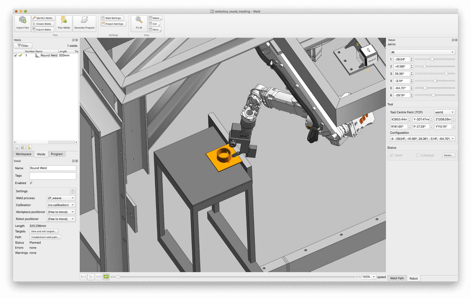
Seam Tracking in Verbotics Weld
Seam tracking functionality is enabled in Verbotics Weld from the weld setting menu. To create a weld with tracking settings do the following:
- Create a weld setting with the required weld parameters.
- Enable a weave and add in the weave settings to call on the robot.
- Enable arc seam tracking.
- Enter the seam tracking settings to call on the robot.
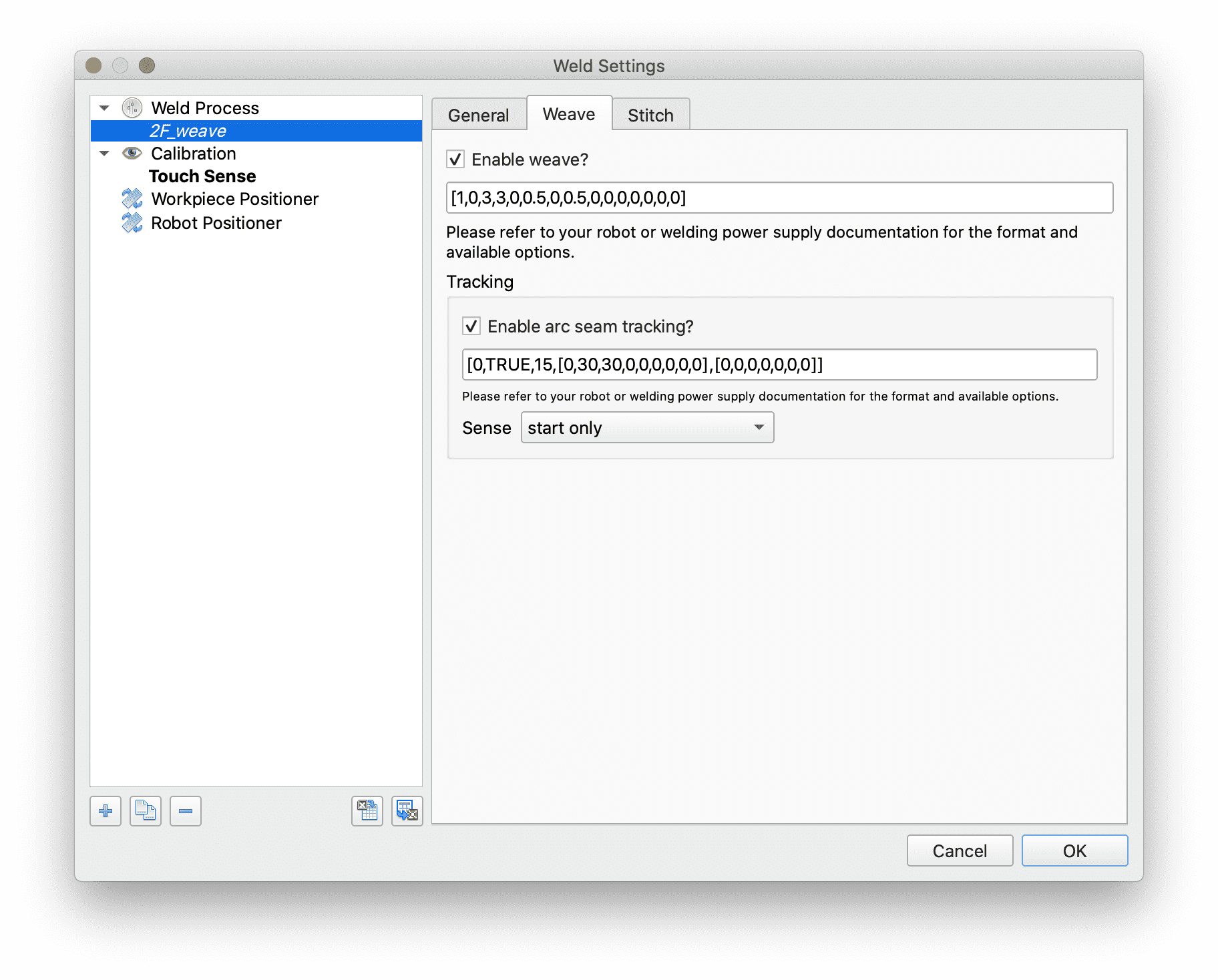
Verbotics will now output this information when these weld settings are used. To determine the weave and tracking settings you should use, please consult the appropriate manual that details these features for your robot.
In Verbotics Weld we also have other options that you can use in conjunction with the tracking settings. For example you may only want to sense the start of the weld, and allow the tracking to follow the weld from there.
Simple Example
Here is a simple example. This fillet weld was planned in Verbotics without path calibration. The part was deliberately mounted to have a large error at the start of the weld to show the effectiveness of seam tracking.
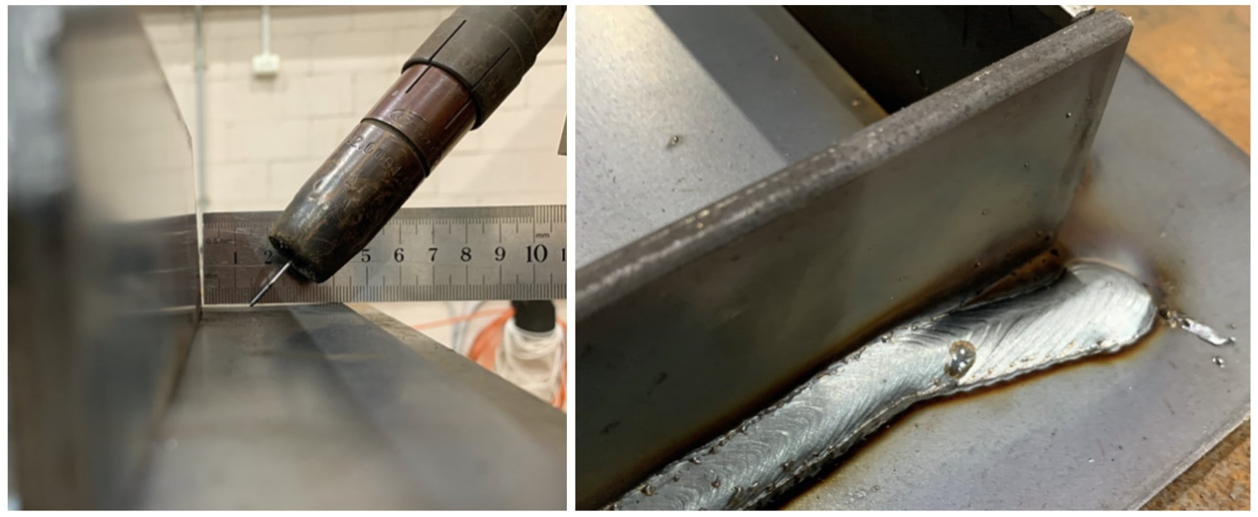
As you can see the robot is able to detect and quickly track back to the weld groove with the appropriate settings. This weld was programmed without any path calibration. In this case we recommend using the Verbotics automatic path calibration routines to create the robot motions to find the start of the weld for best results.
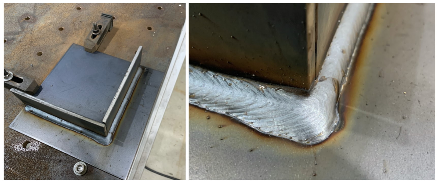
A Corner Weld
Arc tracking can help your robot track a weld around a corner. In this next example we have a weld around a 90 degree corner. Again, the part has been offset slightly so the robot path at the start of the weld is slightly up the plate and then offset along the base by 10mm when the path is around the corner.
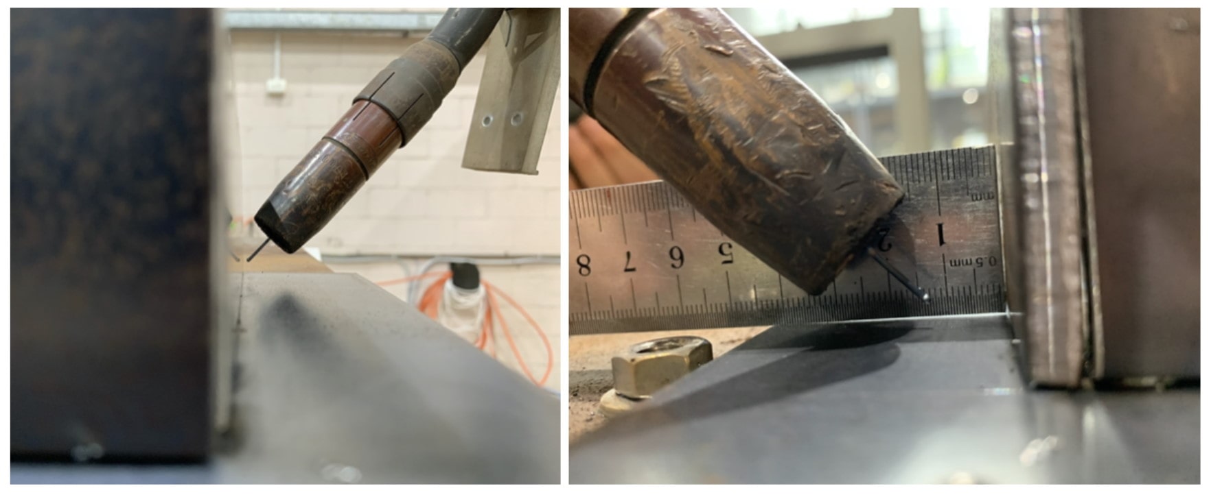
This is the result of that weld path with arc tracking. At the corner where the robot experiences a large step in the tracking error it is able to quickly compensate and keep the weld pool attached to the vertical plate.
Curved Welds
The most useful application for seam tracking is for curved welds. Curved weld paths can have other sources of error that make following the real path difficult. One example we typically see is in bent or folded parts that are drawn with a nominal radius in the CAD model that differs from the real workpiece. Verbotics will output a path for the robot to follow based on the CAD model, however this can lead to poor results if this is different from the actual path required for the workpiece.
Again in this example no path calibration was used, only the path generated straight from Verbotics Weld with seam tracking enabled.
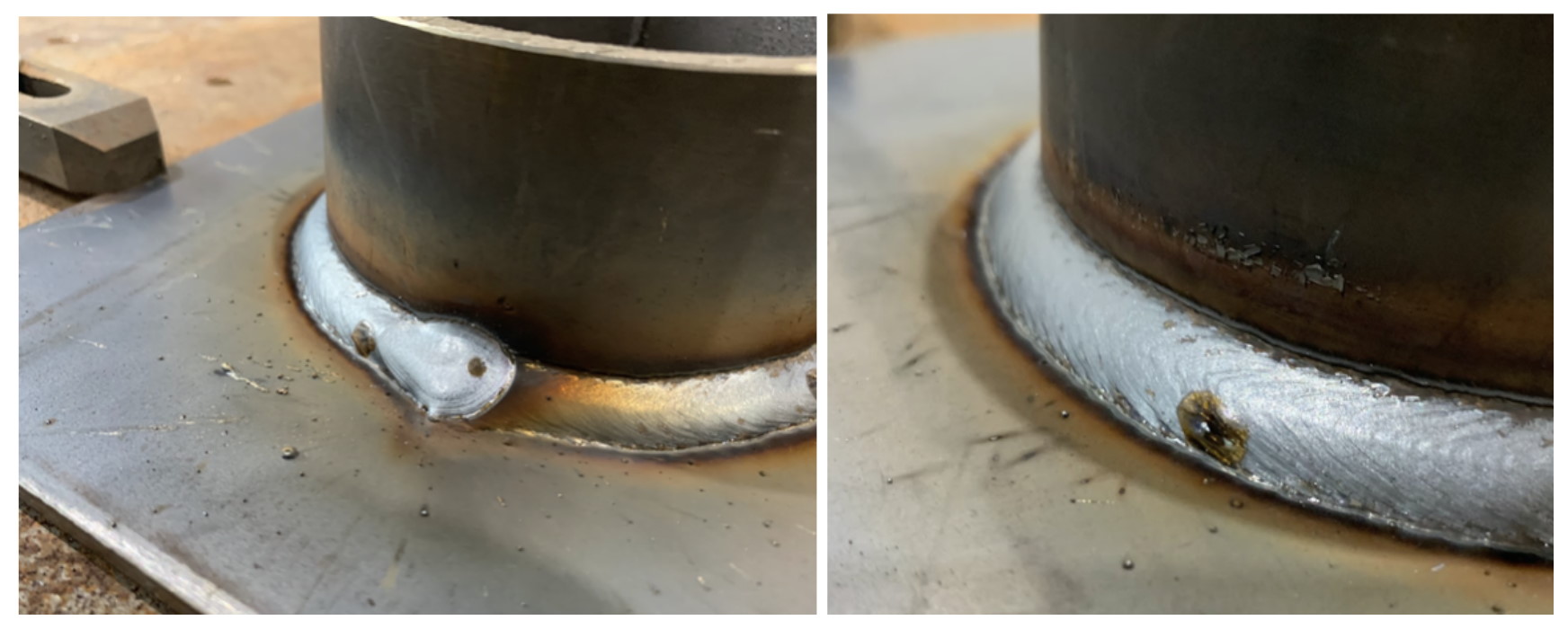
For this circular weld the seam tracking is able to quickly bring the weld path into the weld groove and follow it for the complete circle. The start which was slightly out was covered by the weld end so this is now difficult to see.
Taking this one step further, here is the same part, however one has been pressed into an oval shape to create a noticeable difference between the CAD model where the part is a circle.
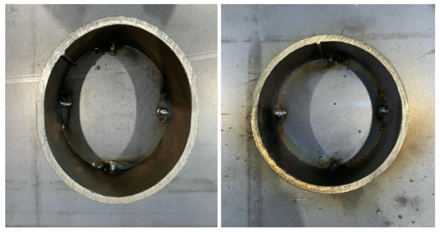
The same program was run that was generated for the circular part. Here are the resulting welds side by side to demonstrate the results that can be obtained from seam tracking.
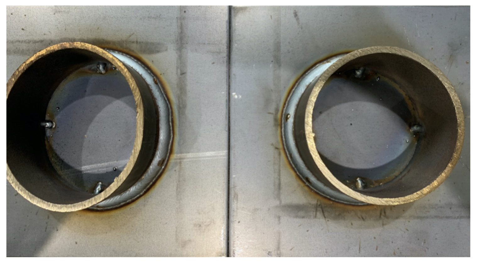
Finally to further illustrate the effect of seam tracking for this case the program was run with tracking disabled to show how the weld would look without any compensation. In these images you can clearly see where the weld has undercut the pipe in one area, and missed it on another.
Conclusion
Seam tracking is a very useful feature to allow your robot to track a weld seam in real time. Coupled with the automatic programming features of Verbotics Weld, your robot can be programmed directly from your CAD models and compensate for variations between the model and the real workpiece. Please contact us if you would like to know more.
These welds were conducted on an ABB IRB2600ID with WeldGuide at the University of Wollongong – Facility for Intelligent Fabrication. The weld programs were created with Verbotics Weld.