What if your robot could see? What if it could sense and weld the part in front of it, all without programming or CAD models? Unveiling our latest development: Verbotics Scan-to-Weld.
This new technology uses a welding robot equipped with a 3D sensor to scan the workpiece. Our smart software then analyses the point cloud data to identify welding paths and understand potential collisions. This then informs our best-in-class automatic robot programming algorithms to create optimised robot welding programs - all without coding, CAD models, or touching a teach pendant.
CAD, Sensor-Based, or a Combination
Previously, our Verbotics Weld software relied on CAD models of the part and any jigging to understand the robot’s environment. We now have the option of using CAD, sensor data, or a combination to best suit your manufacturing. This unlocks new exciting capabilities:

Option 1
CAD Only
If you have accurate CAD models of your parts and jigging, our automatic identifier can use this to identify weld paths and create collision-free robot programs.
The key benefit of using CAD data is the high level of detail and information provided. You can identify weld paths which may not be possible to do from sensor data, as well as plan access inside tight areas or areas that cannot be scanned. You also save the time of not needing a scanning step before welding, and can use the additional structure information in the CAD file to save time. However, complete accurate CAD files are not always available, and this requires the part to be relatively accurately positioned in the workcell.
Option 2
CAD + Sensor
Sensor and CAD data can be combined to identify the location of a workpiece in the workcell, without the need to measure the position. This can be particularly useful for parts placed freely on a table or craned into the workcell.
We can also identify additional jigging, fixturing and clamps not present in the CAD model, and use the sensor data to avoid colliding with these. This is a very powerful combination, where can use the high detail of the CAD model for the part, without having to spend the time to model your jigs and fixtures in detail, or where additional structures such as stiffeners are added to the workpiece.
Option 3
Sensor Only
You can now use Verbotics Weld with no CAD models at all, just real-world sensor data. How this works is detailed below.
Our algorithms are designed to handle both simple and moderately complex geometry - we're not limited to specific shapes or straight lines. However, the result of this will depend on the robot accuracy and performance of the sensor, as well as any areas that are unable to be scanned.
We've also included a powerful set of editing features - so you can adjust the automatic identification result to be exactly what you want to weld.
Key Steps
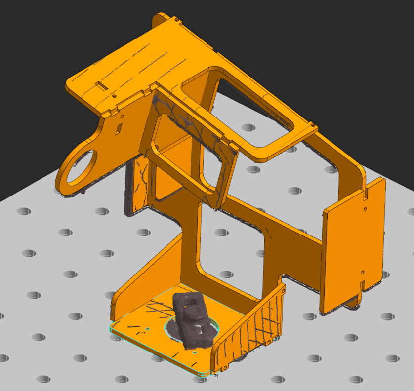
These are the key steps in the sensor data only based programming process. In this example, we’re using a Universal Robot UR10e equipped with a Mech-Mind NANO-ULTRA for smaller parts, but our approach is not tied to one specific sensor, robot type, part size or geometry.
- Scan - a 3D sensor is used to capture the workspace. In the video, we use a robot-mounted (eye-in-hand) sensor, but our technology can also be used with other sensor configurations. Sensing can either be automatic (based on a grid of sensor positions), or hand-guided. In the future we plan to implement automatic environment exploration.
- Align - our software adjusts the exact positions of each scan to account for any mis-alignment. This helps account for both the sensor and robot accuracy.
- Reconstruct - our algorithms convert the raw point cloud data into CAD-style data which can be used for weld identification and collision avoidance. We include editing tools to allow adjusting these results. Any items we don’t identify as part of the welding geometry (such as clamps or fixtures) remain for collision avoidance purposes.
- Identify - our software automatically identifies potential weld seams. The user can select and sequence these as desired.
- Plan - collision-free and optimised welding and sensing paths are created. The paths are optimised according to your desired welding parameters and torch geometry.
- Weld - a ready-to-run robot program is then generated in the robot’s native language. The program includes touch or laser sensing to perform a final fine adjustment before each weld.
Learn More
Want to learn more about our scan-to-weld technology? We’re currently looking for integrator partners who would like to work with us to deploy this technology to their customers. Please contact us, or reach out to us at info@verbotics.com.